Define Kirchhoff's circuit laws:
Kirchhoff's circuit laws are two equalities that deal with the current and potential difference (commonly known as voltage) in the lumped element model of electrical circuits. They were first described in 1845 by German physicist Gustav Kirchhoff. This generalized the work of Georg Ohm and preceded the work of Maxwell. Widely used in electrical engineering, they are also called Kirchhoff's rules.
Kirchhoff's current law (KCL):
or equivalently
- The algebraic sum of currents in a network of conductors meeting at a point is zero.

Kirchhoff's voltage law (KVL)
- The directed sum of the electrical potential differences (voltage) around any closed network is zero, or:
- More simply, the sum of the emfs in any closed loop is equivalent to the sum of the potential drops in that loop, or:
- The algebraic sum of the products of the resistances of the conductors and the currents in them in a closed loop is equal to the total emf available in that loop.
- More simply, the sum of the emfs in any closed loop is equivalent to the sum of the potential drops in that loop, or:


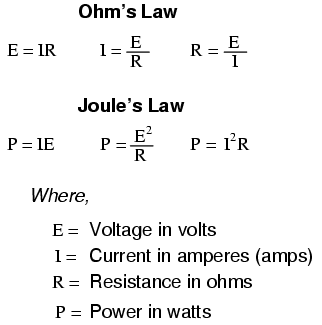
Ohm's Law
Define:- Ohm's law states that the current through a conductor between two points is directly proportional to the potential difference across the two points. Introducing the constant of proportionality, the resistance, one arrives at the usual mathematical equation that describes this relationship

Joule's laws
Define:- Joule's laws are two laws about heat produced by an electric current and the energy dependence of a gas to pressure, volume and temperature.
Joule's first law shows the relation between heat generated by an electric current flowing through a conductor. It is named after James Prescott Joule and shown as:

Ohm's Law Experiment (Video)
Joule's Law Experiment (Video)
1. Define Electrical Transformers:
A transformer is an electrical device, Transfers energy between two
or more circuits through electromagnetic induction.2. History of Transformers:
A wide range of transformer designs is encountered in electronic and electric power applications. Since the invention in 1885 of the first constant potential transformer, transformers have become essential for the AC transmission, distribution, and utilization of electrical energy.
3. Parts of transformers:
3.2) CONSERVATOR: it is used to provide adequate space for the expansion of oil when transformer is loaded or when ambient temperature changes.
3.3) SILICA GEL BREATHER: it sucks the moisture from the air which is taken by transformer so that dry air is taken by transformer.
3.4) DOUBLE DIAPHRAGM EXPLOSION VENT: it is used to discharge excess pressure in the atmosphere when excess pressure is developed inside the transformer during loading.
3.5) OIL LEVEL INDICATOR: it is used to show the oil level in the transformer.
3.6) WINDING AND OIL TEMPERATURE INDICATOR: used to show the temperature of transformer winding and Oil winding.
3.7) RADIATORS: these are used for cooling of the transformer oil.
4. Basic working principles:
A transformer can be defined as a static device
which helps in the transformation of electric power in one circuit to electric
power of the same frequency in another circuit. The voltage can be raised or
lowered in a circuit, but with a proportional increase or decrease in the
current ratings.
The main principle of operation of a transformer
is mutual inductance between two circuits which is linked by a common magnetic
flux. A basic transformer consists of two coils that are electrically separate
and inductive, but are magnetically linked through a path of reluctance.

- Where:
- VP - is the Primary Voltage
- VS - is the Secondary Voltage
- NP - is the Number of Primary Windings
- NS - is the Number of Secondary Windings
- Φ (phi) - is the Flux Linkage
Notice that the two coil windings are not electrically
connected but are only linked magnetically. A single-phase transformer can
operate to either increase or decrease the voltage applied to the primary
winding. When a transformer is used to “increase” the voltage on its secondary
winding with respect to the primary, it is called a Step-up transformer.
When it is used to “decrease” the voltage on the secondary winding with respect
to the primary it is called a Step-down transformer.
5.1) Transformers turns ratio


5.2) Transformer Efficiency


6. Types of transformer
6.1) Autotransformer: Transformer in which part of the winding is common to both
primary and secondary circuits.
6.2) Capacitor voltage transformer:
Transformer in which capacitor divider is used to reduce high voltage before
application to the primary winding.
6.3) Distribution
transformer, power transformer:
International standards make a distinction in terms of distribution
transformers being used to distribute energy from transmission lines and
networks for local consumption and power transformers being used to transfer
electric energy between the generator and distribution primary circuits.
6.4) Phase angle regulating transformer:
A specialized transformer used to control the flow of real power on three-phase
electricity transmission networks.
6.5) Scott-T transformer:
Transformer used for phase transformation from three-phase to two-phase and vice versa.
6.6) Poly phase transformer: Any transformer with more than one phase.
6.7) Grounding
transformer: Transformer used for grounding
three-phase circuits to create a neutral in a three wire system, using a
wye-delta transformer or more commonly, a zigzag grounding winding.
6.8) Leakage transformer:
Transformer that has loosely coupled windings.
6.9) Resonant transformer: Transformer that uses resonance to generate a high
secondary voltage.
6.10) Audio transformer:
Transformer used in audio equipment.
6.11) Output transformer: Transformer used to match the output of a valve amplifier
to its load.
6.12) Instrument transformer: Potential or current transformer used to accurately and
safely represent voltage, current or phase position of high voltage or high
power circuits.
Electrical voltage is defined as electric potential
difference between two points of an electric field.
Using water pipe analogy, we can visualize the voltage as height difference that makes the water flow down.
φ2 is the electric potential at point #2 in volts (V).
φ1 is the electric potential at point #1 in volts (V).
In an electrical circuit, the electrical voltage V in volts (V) is equal to the energy consumption E in joules (J)
divided by the electric charge Q in coulombs (C).

V1 - voltage source or voltage drop in volts (V).
V2 - voltage source or voltage drop in volts (V).
V3 - voltage source or voltage drop in volts (V).
V1 - voltage source or voltage drop in volts (V).
V2 - voltage source or voltage drop in volts (V).
V3 - voltage source or voltage drop in volts (V).

The voltage drop on a resistor can be calculated from the resistor's resistance and the resistor's current, using Ohm's law:
The voltmeter has very high resistance, so it almost does not affect the measured circuit.
Using water pipe analogy, we can visualize the voltage as height difference that makes the water flow down.
V = φ2 - φ1
V is the voltage
between point 2 and 1 in
volts (V).φ2 is the electric potential at point #2 in volts (V).
φ1 is the electric potential at point #1 in volts (V).
In an electrical circuit, the electrical voltage V in volts (V) is equal to the energy consumption E in joules (J)
divided by the electric charge Q in coulombs (C).
V is the voltage
measured in
volts (V)
E is the energy measured in joules
(J)
Q is the electric charge
measured in coulombs (C)
Voltage in series
The total voltage of several voltage sources or voltage drops in series is their sum.
VT = V1 +
V2 + V3 +...
VT - the equivalent voltage source or
voltage drop in volts (V).V1 - voltage source or voltage drop in volts (V).
V2 - voltage source or voltage drop in volts (V).
V3 - voltage source or voltage drop in volts (V).
Voltage in parallel
Voltage sources or voltage drops in parallel have equal voltage.
VT = V1 =
V2 = V3 =...
VT - the equivalent voltage source or
voltage drop in volts (V).V1 - voltage source or voltage drop in volts (V).
V2 - voltage source or voltage drop in volts (V).
V3 - voltage source or voltage drop in volts (V).
Voltage divider
For electrical circuit with resistors (or other impedance) in series, the voltage drop Vi on resistor Ri is:Kirchhoff's voltage law (KVL)
The sum of voltage drops at a current loop is zero.
∑ Vk = 0
DC circuit
Direct current (DC) is generated by a constant voltage source like a battery or DC voltage source.The voltage drop on a resistor can be calculated from the resistor's resistance and the resistor's current, using Ohm's law:
Voltage calculation with Ohm's law
VR =
IR × R
VR
- voltage drop on the resistor measured in volts (V)
IR
- current flow through the resistor measured in amperes (A)
R - resistance of the resistor
measured in ohms (Ω)
AC circuit
Alternating current is generated by a sinusoidal voltage source.Ohm's law
VZ =
IZ × Z
VZ
- voltage drop on the load measured in volts (V)
IZ -
current flow through the load measured in amperes
(A)
Z - impedance of the load
measured in ohms (Ω)
Momentary voltage
v(t) = Vmax ×
sin(ωt+θ)
v(t)
- voltage at time t, measured in volts (V).
Vmax - maximal voltage (=amplitude of
sine), measured in volts (V).
ω
- angular frequency measured in radians per second (rad/s).
t
- time, measured in seconds (s).
θ
- phase of sine wave in radians (rad).
RMS (effective) voltage
Vrms = Veff
= Vmax / √2 ≈
0.707 Vmax
Vrms - RMS voltage, measured in volts
(V).
Vmax - maximal voltage (=amplitude of
sine), measured in volts (V).
Peak-to-peak voltage
Vp-p =
2Vmax
Voltage drop
Voltage drop is the drop of electrical potential or potential difference on the load in an electrical circuit.Voltage Measurement
Electrical voltage is measured with Voltmeter. The Voltmeter is connected in parallel to the measured component or circuit.The voltmeter has very high resistance, so it almost does not affect the measured circuit.


